© Special Astrophysical Observatory of the Russian Academy of Sciences
The
ESPriF
echelle
spectrograph
is
designed
for
observing
star-like
objects
at
the
primary
focus
of
the
BTA
in
the
wavelength
range
from
3800
Å
to
10,800
Å
with
a
spectral
resolution
R
from
15,000
to
30,000
,
both
in
conventional
spectroscopy
mode
and
spectropolarimetry
mode.
The
evaluation
of
ESPriF's
performance
showed
that
it
is
possible
to
observe
star-like
objects
with
a
magnitude
up
to
14
m
in
the
V
band
with
the
resolving power R =
15,000
.
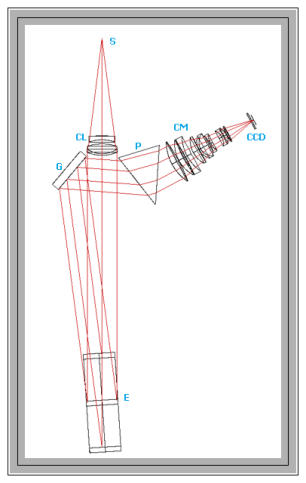
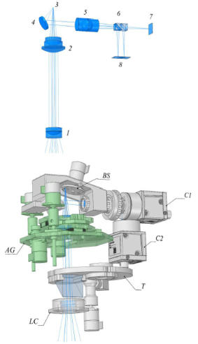
The Spectrograph Design
The optical layout of the ESPriF spectral module is shown in the figure on the top-right. A divergent light beam with an aperture of A=1:4 from the entrance slit S enters the lens collimator CL . Next, the collimated beam reaches the echelle grating E , which operates outside the principal plane. The light then hits the cross-dispersion diffraction grating G , located in close proximity to the collimator. The cross-dispersion diffraction grating provides the necessary separation of spectral orders at the long-wavelength part of the operating range. Additional separation of the short-wavelength orders is produced by the prism P. Subsequently, the camera CM forms a spectral image on the CCD detector. The collimator is a three-lens apochromat. Its focal length is 300 mm, and the aperture diameter is 75 mm. The collimator objective assembly is equipped with a micrometer focusing mechanism because the astigmatism introduced by the echelle gratings with a large blaze angle is sensitive to the collimation quality of the incident beam. The echelle grating has a blaze angle of θ_B = 72° (tan θ B = 3.08 ), and the ruled surface dimensions are 250 x 80 mm. The average diffraction angle is equal to the angle of incidence, i.e., β = α = θ B , and the angle between the principal plane of the echelle and the axis of the incident beam is γ = 7.5° . Thus, the average tilt angle of the spectral lines is χ ~ 40° . The cross-dispersion unit consists of two optical elements: a reflecting diffraction grating operating in the first order, and a prism. The combination of a prism and a diffraction grating is used to utilize the detector’s working area more effectively. The parameters of the prism and the diffraction grating were chosen to enable simultaneous recording of the 3800–10,800 ÅÅ range, with order separation sufficient for the use a polarization analyzer or an image slicer without requiring reconfiguration of the spectrograph layout. The entire operating range covers 49 spectral orders. Scheme of the spectrograph's input module (IM) The central figure on the right shows the light-path; the lower figure shows the main components and assemblies: 1 and 2 — elements of the afocal reducer, 3 — the slit (decker) position, 4 and 5 — decker viewing optics, 6 — beam splitter elements of the defocusing detector, 7 and 8 — decker viewing sensors. LC — lens-based pre-focal collimator, T — turret with phase-shifting plates and a flip prism for calibration light, AG — auto- guiding module with a movable objective, BS — interchangeable set of slits (0.5”, 0.75”, and 1.0”), C1 — input slit viewing camera, C2 — autofocusing channel. Structural elements are not shown.Useful References
V. E. Panchuk, V. G. Klochkova, M. V. Yushkin, G. V. Yakopov, Yu. B. Verich, and M. E. Sachkov, 2017 // Stars: from Collapse to Collapse ASP Conference Series, Vol. 510, Yu. Yu. Balega, D. O. Kudryavtsev, I. I. Romanyuk, and I. A. Yakunin, eds. © 2017 Astronomical Society of the Pacific Yushkin M. V., Emelianov E. V., Verich Yu. B. 2023 // Astrophysical Bulletin, Volume 78, Issue 4, pp. 613-621