|
A multielement arrays
in the radio telescopes focus.
E.K. Majorova, V.B.Khaikin, SAO RAS
|
Performance data of radio telescopes with a multielement focal arrays are
investigated. The problem of optimization of the array design, the elements
of which are horizontally oriented strip radiators, are discussed with
reference to RATAN-600 and a paraboloid. A computation of beam patterns of
these telescopes operated in the mode of multibeam reception with the use
of different modifications of focal arrays is performed. A "terrace-like"
design of focal array for illumination of non-symmetric secondary mirror of
RATAN-600 and symmetric mirrors (paraboloids) is proposed.
|
|
The multibeam operation of a radiotelescope can be implemented by placing a
matrix of primary feeds in its focal plane. This kind of multielement receiving
array at the focus of a reflector radio telescope widens essentially its
field of view, improves the integral sensitivity, speeds up the imaging of
extended sources, reduces the influence of the atmosphere.
A matrix of primary feeds is placed on the focal line of the secondary mirror of
RATAN-600. The secondary mirror is a non-symmetric parabolic cylinder with
a horizontal generant, on the focal line of which (X axis in Fig.1(b))
primary feed cabins are located, which enables simultaneous observations at
several wavelengths. This design of the secondary mirror is convenient for the
multibeam mode of operation of the radio telescope with the one-dimensional,
two-dimensional and three-dimensional arrays.
|
| 
|
|
FIg.1.
The section of the secondary mirror in the vertical (a) and horizontal (b)
planes. 1 -- the parabolic mirror, 2 -- the primary feed.
|
|
The number of elements in the array is determined by the size of aberretion-
free zone of the radio telescope, which, under the condition of two-mirror
focusing system, depends on the elevation H of the sourse being observed.
Fig.2 shows an computed aberration curves of RATAN-600. By the aberration curves
we mean the relationships between the maximum of the telescope BP,
Fmax, and the removal of the primary feed from the focus.
Examples of a computed and experimental curves give in section
"Experimental investigations of the beam
pattern RATAN-600".
|
 |
Fig.2.
The aberration curves at the wavelength 10 mm with the removal of the primary
feed along the focal line of the secondary mirror (X axis) on the elevation
H=0o, 30o, 60o, 90o.
The regime of the two-mirror focusing system with the full aperture.
|
|
The one-dimensional array placed on the focal line of the secondary mirror is
the most efficient when observing sources with elevation close to 90o,
since under this condition the aberration-free zone of RATAN-600 is maximum.
With decreasing elevation of the source, the aberration-free zone narrows
rapidly. As to the spurious polarization, it is minimum at altitude close to
zero and grows monotonically with increasing elevation of the sourse. For this
reason, in polarization measurement the three-mirror focusing system of
RATAN-600 with the periscopic flat mirror ("South+Flat" mode), in which the
circular mirror is set vertically to the altitude H=0o, appears to
be more preferable. The number of strip radiators in the one-dimensional focal
array at the wavelength 10 mm in observing near-zenith sources may thus be
160 elements, whereas for effective reception of radiation from low
elevation souoces their number should not be larger than 10.
To assess the possibility of using two- and three-dimensional arrays in focal
region of RATAN-600, calcucations of the vertical BP were carried out with
arbitrary removal of the primary feed from the focus F on the plane A
(Fig.1(Á)). Curves 1--9 in Fig.3 show the vertical BP at the wave of 10 mm
with a removal of the primary feed from the focus by quantity 5 mm and
locating it at points 1, 2, 3, 4, 5, 6, 7, 8 , 9 (Fig.3(b)) for H=0o,
10o, 30o, 50o É 85o.
The beam patterns of the primary feeds and the real sizes of the focusing
system of RATAN-600 were specified in the calculation. In each of the locations
the maximum of the primary feed BP makes an angle
 =50o with the horizon. =50o with the horizon.
|
|
Fig.3.
BP of RATAN-600 at the wavelength of 10 mm
with a removal of the primary feed from the focus by quantity 5 mm and
locating it at points (1 - 9) - (b).
(a) - H=0o, (c) - 10o, (d) - 30o, (e) -
50o, (f) - 85o.
The schematic view of location of feeds in the vertical section of the
secondary mirror - (b).
|
|
It can be seen from the curves given in Fig.3, that the beam deflection of
the BP by means of the removal of the primary feed from the focus is possible
only at altitudes close to zero. Therefore the two-dimensional flat
arrays can be use or in the mode of two-mirror focusing system
"South+Flat", or in the mode of the observations with one sector of the
RATAN-600, but only for the sources whose elevations close to zero.
In the view of obtaining a maximum signal the array elements must locate
or along axis Y or along the direction perpendicular to direction of radiation
primary feed (points 4-8). The maxima of radiation of individual elements of
the array must make an angle of =50o.
with the horizon.
|
 |
 |
|
Fig.4.
The schematic view of the "terrace" arrangement of the primary radiators in
the focal region of the secondary mirror of RATAN-600 (vertical section)
(from the left). 1 - the parabolic mirror, 2 - the fences of the primary radiators.
The examples of "terrace" design of the multielement receiving array with
microstrip radiators (from the right).
|
|
Fig.5.
The vertical BP of radio telescope RATAN-600 under the condition "South +Flat"
at the wave of 10 mm with location in its focal region of the receiving array
of "terrace" (a) and flat (b) design.
|
|
A "terrace" design of the thee-dimensional array consisting of linear strip
arrays (LSA) of radiators is considered. These fences are parallel to the focal line
of the sacondary mirror and shifted with respect to each other in the vertical
plane by a value h, the distance between the radiators in the fences is set
by the parameter l (Fig.4). Such a design is not only more simple in realization, but also turns out to be
more optimum in energy characteristics.
It is well seen from Fig.5 that with the use of the "terrace" design the
drop in the maxima of the BP of individual beams is less than with the
flat design. With the same separation of the elements and their number
(N = 7) the drop in signal in the marginal elements of the array amounts
to about 40% in the case of the flat array, while for the "terrace" array it is
no more than 15%.
Manual influence of the elements in
the "terrace" design is less essentially comparing to the flat array [1].
|
 |
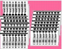
Fig.6.
The isophotes of the two-dimensional multibeam BP of the RATAN-600 with
location in it focal region of array of "terrace-like" design at the wave
1 cm. The BP of the outermost and central elements of focal array are shown.
A total number of beams in this mode can amound to 7x10 ( 7 - in the vertical
and 10 - in the horizontal planes).
|
|
The arrays of "terrace-like" design can be used at the RATAN-600 in the mode
of the observations with one sector (at altitudes close to zero) and
in the mode "South+Flat". The optimum number of LSA in such arrays is 7 - 8.
With allowance made for the aberration curve 1 in Fig.2, along the focal line
of RATAN-600 each LSA can hold no more 10 elements. Thus, in these modes of the
radio telescope operation one can implement multibeam observations with the
three-demensional "terrace-like" array a total number of receiving elements of
about 70. In the mode of the "radio-Schmidt" telescope, where the aberration-free
zone is substantially larger, the number of elements in the three-dimensional
array may reach 1000. Observations can be made at any fixed source altitude,
provided that it coincides with the altitude the "radio-Schmidt is designed for,
with an an antenna aperture size no more than 150 m.
|
 |
 |
 |
 |
|
òÉÓ.7.
The diagram of the "terrace" design of the array in the focal range of a
paraboloid (circular alternative) in the radial section (a), in the frontal
section (b). 1 - the paraboloid, 2 - the primary radiators.
|
|
A focal arrays of "terrace" design can be employed in paraboloids. Fig.7
displays examples of "terrace" design of the array, which take account of axial
symmetry of the paraboloids (circular variant). The location of the radiators
is shown in one of the radial sections of the paraboloid - in the plane that
passes throught the radius of the circle, which is the aperture of the paraboloid
and its axis of symmetry (Fig.7a), and in the frontal section - in the plane
perpendicular to the paraboloid axis (Fig.7b). In this design the radiators are
arranged in rings shifted with respect to each other in depth by the quantity h.
Apart from the axially symmetric array construction, rectangular design shown
in Fig.9 are possible. In the plane (X0Y) the LSA of the radiators are shifted
by h, and location of the radiators in this plane is the same as in Fig.7a.
|
|
Fig.8.
The BP of a parabolic radio telescope in the radial planes at the 10 mm
wave with a "terrace" array (circular alternative) placed in its focal region.
N is the number of elements in the radial section.
|
|
The BP of the parabolic antenna in the focal plane of which strip radiators
are placed, which form a "terrace" array are displayed in Fig.8 (circular
alternative) and in Fig.10 (restangular alternative). N is the number of array
elements in each of the radial section for circular alternative or in each of
the LSA for restangular alternative. The beam patterns were calculated for
optimum values of h and l. Location of array relative to the paraboloid focus
also were optimized.
|
|
Fig.9.
The schematic view of the "terrace" array (rectangular alternative) in the
focal region of a paraboloid. 1 - the paraboloid, 2 - the primary radiators.
|
|
Fig.10.
The BP of a paraboloid at the 10 mm wavelength in the Y0Z with the "terrace"
array (rectangular alternative) placed in its focal region.
|
|
The BP of a paraboloid in the plane X0Y (rectangular alternative of an array
design) coincide with the BP of the axially symmetric array in its radial
section, the shape of the multibeam BP in the plane Y0Z are displayed in Fig.10.
The "terrace" design of the array is thus quite suitable for paraboloids
and, in same cases, has even certain advantages over the flat array.
With the number of elements 3È3 and 4È4 the "terrace" arrangement of the
elements makes it possible to get a multibeam BP with the same level
of signal in all beams, that is imposible to get with the flat array.
|
|
[1]
Khaikin V.B., Majorova E.K., Parijskij Yu.N., Parnes M.D. et al.,
Proceedings of international conference "Perspective on radioastronomy:
technologies for large antenna arrays", Dwingeloo, the Netherlands, April,1999,
|
|