|
A.B.Berlin, G.M.Timofeyeva
St.Petersburg Branch, Special Astrophysical Oservatory of Russian
Academy of Sciences
65 Pulkovskoye Shosse, St.Petersburg, 196140, Russia
E-mail: abb@fsao.spb.su
N.A.Nizhelsky, A.V.Bogdantsov
Special Astrophysical Observatory of Russian Academy of Sciences
Nyzhny Arkhyz, Karachai-Cherkessia, 357147, Russia
E-mail: nizh@rs.ratan.sao.ru
O.M.Pylypenko, V.M.Chmil', Yu.N.Meshkov, A.N.Zdor
"Saturn" Scientific and Productive Open Join-Stock Company
2B, pr.50 Richya Zhowtnya, Kyiv, 252148, Ukraine
E-mail: alr@jssaturn.kiev.ua
MARS ( MAtrix Radiometric System ) project is reported.
The instrument is intended to be used as a possible radiometric support to
the "Cosmological Gene" project. MARS is planned to be installed in the focal
line of the RATAN-600 radio telescope.
An input signal of two orthogonal linear polarizations is transferred via
orthomode transdusers, 128 units in line, to 256 radiometric modules.
Each module of the system is an independent noise-added, gain-balanced
straight-amplifier radiometer. First prototype models of the radiometric
module and of the noise generator unit design and test results are presented.
MMICs and HEMT chip transistors as active components were applied.
For one radiometric unit, 210K noise temperature, 65 dB gain and 6 GHz
bandwidth at 30 GHz center frequency were measured.
1. Introduction
An evaluation was undertaken to choose the appropriate radiometric
support solution for the "Cosmological Gene" project[1] for the
RATAN-600 radio telescope [2,3]. Two concepts were selected for final
comparison: a beam-switched, cryogenically cooled down to 15K radiometer with
a quasi-optical feed system and an uncooled matrix concept.
The latter ( matrix ) concept was chosen for a combination of
reasons, among them a greater application versatility and future opportunity
to enhance sensitivity considerably by applying some kind of cryocooling.
2. Design goals and basic concept
The MAtrix Radiometric System ( abbreviation: MARS ) project is intended to
learn what can be done by comparatively simple means to provide a radiometric
support for the RATAN-600 the "Cosmological Gene" project.
Main goals of the MARS project are as follows:
- Implementation of radiometric sensitivity, for each of two orthogonal
linear polarizations, less than 1 mK (1 sec integration time) for the
central frequency 30 GHz and bandwidth up to 6 GHz.
- The focal line up to 1750 mm long can be used.
- It might be as well to use commercially available components only.
- No cryocooling needs to be applied at the first step of design.
- It is necessary to accomplish an interchangeability of the building
blocks of the matrix.
- Compatibility with standard laboratory microwave test equipment must
be provided to verify all basic parameters of the matrix components
(frequency band, gain, noise temperature, feed pattern).
- Maintenance and reliability problems have to be taken into account to
to ensure the continuous operation of the system during up to five years .
Figure 1. MARSproject building block concept
The idea of the design is shown in Fig. 1. Quasi-scalar input feeds
(128 units) and orthomode transdusers (OMT) following after then are
placed along the RATAN-600 focal line with a 13.5 mm spacing.
Two MARS elementary radiometers are connected to each OMT,
256 radiometric modules (RM) in all. Each elementary radiometer is of single
beam, noise-added, gain-balanced mode of operation. From the point of view
of theoretic sensitivity, this mode of operation may be considered as being
quite close to the switched mode and, like the latter, enables the gain
instability to be avoided [3].
We can consider as an advantage of the
noise-added mode the fact that input feeder is absolutely free and has no
lossy active devices. We are not going to use the total power mode to avoid
the "knee frequency" problem. The mode of operation accepted is very
sensitive to input noise temperature instability ( like the total power mode ),
but, it is known from our experience, this problem could be overcome by
means of very good power supply and thermostat regulation
(better than 10-3).
Noise-adding and calibrating signals are fed to the input feeds
of the matrix by means of open-space coupling from the source placed
at the secondary mirror surface at a distance of about 2.5 meters from the
focal line. Open-space coupling of the noise-adding signal was successfully
applied for radiometry previously [4].
The working cycle of the noise-added, gain-balanced radiometer is
locked-in to the LF square wave driving voltage. During one half-period of
the driving voltage the noise-adding generator is turned-off and the gain
modulator ( which is controlled attenuator actually ) is open ( minimal loss
state ). During the other half-period of the driving voltage the noise-adding
generator is turned-on and the gain modulator is closed.
In this connection,
noise-adding signal at the input feed is of the order
of TSYS, and gain modulator ( attenuator ) has
losses of the order of 13 dB. The balance, usually performed before the
observing session, means, that there is no difference in the
post-detector output signals for these two half-periods, which can be
accomplished by fine tuning of the modulator ( attenuator )
loss for "closed" state around 13 dB level.
3. Active modules design
3.1. Radiometric module
Each radiometric module ( RM ), one of 256 identical units, is of straight
amplifier design, without frequency conversion. The structure of the RM
is shown in Figure 2.
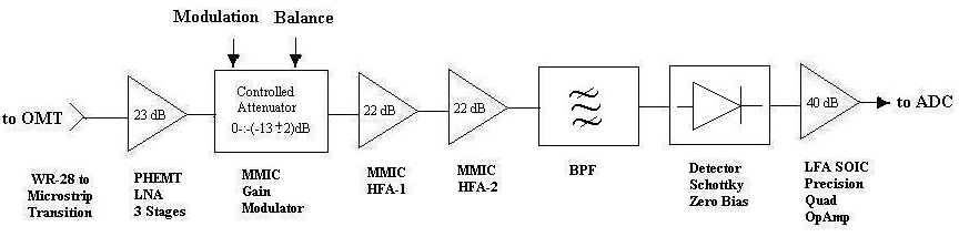
Figure 2. Radiometric module configuration
The RM consists of ( sequentially ): WR28 to microstrip transition,
LNA, gain modulator, high frequency amplifiers, band-pass filter, detector
and low frequency amplifier.
The LNA is of three-stage hybrid technology design with EC2612
United Monolithic Semiconductors PHEMT transistor chips. The matching
circuits are made by thin-film technology on a .2 mm thickness fused quartz
substrate. The capacitive matching tuners were used for the fine tuning
of the amplifier. The LNA parameters: frequency band is 27-33 GHz,
gain  23 dB, gain ripple 23 dB, gain ripple  1.5 dB, input/output VSWR is 1.9/1.5,
equivalent noise temperature, including waveguide to microstrip loss and
averaged for full bandwidth, is 190 K. The LNA noise budget, taking into
account the LNA components contribution ( calculated ),
is shown in Table 1. 1.5 dB, input/output VSWR is 1.9/1.5,
equivalent noise temperature, including waveguide to microstrip loss and
averaged for full bandwidth, is 190 K. The LNA noise budget, taking into
account the LNA components contribution ( calculated ),
is shown in Table 1.
Table 1. LNA noise budget
| | Waveguide
to Microstrip
Transition |
Input
Matching
Network | First
Stage
Transistor |
Subsequent
Stages |
Transmission
Coefficient
(Loss,Gain),dB |
-0.3 | -0.3 |
8.0 | 14.3 |
Inherent
Noise
Temperature,K |
21 | 21 |
110 | 180 |
Noise Contribution
to the
Equivalent Input
Noise Temperature,K |
21 | 23 |
126 | 33 |
Equivalent Input Noise Temperature of the LNA,K
(averaged for  F = 6 GHz) F = 6 GHz) |
190 |
The controlled attenuator MMIC HMMC-1002 of the Hewlett-Packard is
used as the gain modulator with TTL driving square-wave voltage and with
additional DC ( 0...5 V ) control voltage for the modulation depth
trimming ( i.e., balancing of the radiometer ).
The dependence of the wavefront steepness of the modulated signal
envelope on the attenuator chip illuminance was detected. To make the
fronts of the envelope faster, backlighting of the attenuator chip by
IR LED chip was introduced in the design.
Two MMICs, connected in series, were used as the high frequency
amplifiers. We tested HMMC-5040 of the Hewlett-Packard and AA038N1-00
of the Alpha Ind. successfully.
The band-pass filter incorporates seven half-wave transmission line
resonators, made by thin-film technology on a .2-mm thickness fused quartz
substrate and placed into the channel of 3 mm by 1.5 mm cross-section.
The detector applied is a zero bias beamlead GaAs Schottky diode of
Hewlett-Packard.
3.2. Noise generators unit
The noise generators unit serves as a noise power source for the
noise-adding and calibration purposes. The unit includes two identical
noise generator (NG) modules. The NG-1 module provides modulated
noise-adding power to the feed inputs of all radiometric modules via open
space coupling. The NG-2 module provides calibrating noise power, which
can be switched on and off according to the observing session program and
is fed to the same emitter, as the NG-1, via a waveguide directional coupler.
The structure of the unit is shown in Figure 3.
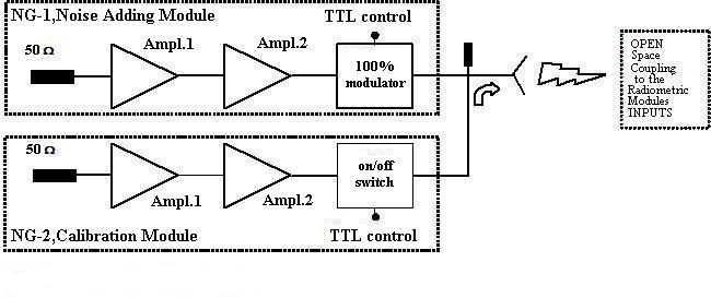
Figure 3. Noise generators unit structure
The noise generators modules NG-1 and NG-2 are of identical design.
Two MMIC amplifiers, connected in-series, ( of the same type, as for
radiometric module ) with matched load at the input represent the
amplified-noise generator proper. The same attenuator chip, as for the RM,
is used as the control device for both modules. It plays the part of
a 100%-modulator for the noise-adding module and of an on/off switch for
the calibration module with TTL control.
4. Results
The radiometric and the noise-adding modules were composed at a laboratory
to form a noise-adding radiometer. The bandwidth-averaged noise equivalent
temperature of the device was measured radiometrically using hot
(ambient temperature) and cold (liquid nitrogen) loads; the
result is TN 210 K.
This yields a sensitivity ( = 1 sec,
TSYS = 260 K, = 1 sec,
TSYS = 260 K,
 F = 6 GHz)
of order of 5.5 mK, and for one polarization with all the matrix about
0.5 mK. We hope that a more sophisticated design of the LNA can reduce its
noise. Further progress can be achieved with LNA cooling down to,
let us say, the liquid nitrogen temperature.
Photographs of the radiometric module and of the noise generator
module are shown in Figure 4 respectively. F = 6 GHz)
of order of 5.5 mK, and for one polarization with all the matrix about
0.5 mK. We hope that a more sophisticated design of the LNA can reduce its
noise. Further progress can be achieved with LNA cooling down to,
let us say, the liquid nitrogen temperature.
Photographs of the radiometric module and of the noise generator
module are shown in Figure 4 respectively.
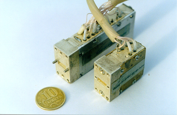
Figure 4. Photograph of the radiometric module and
of the noise generator module
5. Conclusion
The MARS project concept was proposed and evaluated as
a radiometric matrix decision for 1 cm wavelength with a 6 GHz bandwidth.
The prototype of the noise-added, gain-balanced radiometer developed from
radiometric and noise-adding modules was tested and 210 K noise temperature
was measured, which yields one polarization matrix (128 elements)
sensitivity of about 0.5 mK.
Acknowledgements
The authors wish to thank Professor Yu.N.Parijskij for first calling
our attention to the MARS project and for his encouragement and support.
We would like to thank also Yu.N.Konovalov and S.S.Yermolenko for their
suggestions concerning the OMT mechanical design and assembly and for
their expertise in manufacturing of the OMT mechanical parts.
This work was partially supported by grants of INTAS,
# 97-1192, RFBR, # 99-02-17114,
CCPP "Cosmion", "Astronomy" program # 2.1.2.7.
References
- 1. Yu.N.Parijskij "New generation CMBA experiment "Cosmological Gene"
at RATAN". In this issue.
See also: http://www.sao.ru and http://brown.nord.nw.ru
- 2. Yu.N.Parijskij "RATAN-600: the world biggest reflector at the
"cross roads". IEEE AP Mag.
Vol.35, No.4, pp.7-12, Aug. 1993.
- 3. Yu.N. Parijskij, D.V. Korolkov "Experiment Cold: the first deep
sky survey with the
RATAN-600 radio telescope". Soviet Scientific Reviews/Section
E. Astrophysics and space physics reviews,
ed. by R.A. Syunyaev, Harwood Academic Publishers GmbH, vol.5,
pp.39-179, 1986.
- 4. A.E. Wright et. al. "A novel noise-adding radiometer".
Proc. ASA 6, (4), pp.512-516, 1986.
|